

Arduino Smart Lamp
Published on Apr 25, 2020 by Sachin.
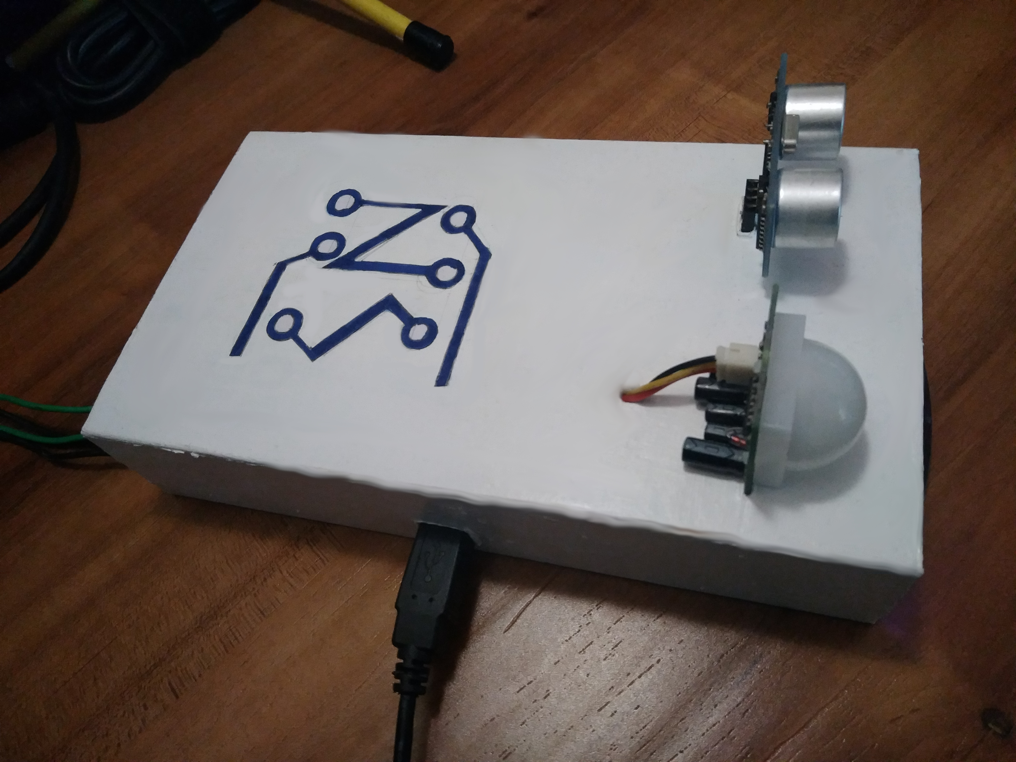
Figure 1: Final Setup - USB TTL serial cable featuring FTDI and USB Power source connected at the bottom. The wires at the rear are connected to the 5V 4C Relay.
I recently bought a new Larrissa Floor Lamp(Figure 2) for the Study room. The Lamp has two LED Bulbs which can be operated individually by separate switch. The placement of the Lamp is good enough to sufficiently lit the room however, the switches are not easily accessible from the study table. Generally a single LED(I’ll denote both LEDs as Lamp1 & Lamp2 henceforth) is enough during the day but during the Video call, I have to switch ON both the Lamps to have enough light in the room. I often forget to switch OFF the Lamp while leaving the room for short breaks which cause Power wastage. This lead me to automate the behavior of the Lamp when I’m not in the room for certain amount of time. I soon began to look for accessories available in my arsenal and I found two Arduino’s, a PIR(Passive IR sensor), HC-SRO4, 5v Relay, an old Remote Control and couple of connecting wires just enough to get started.
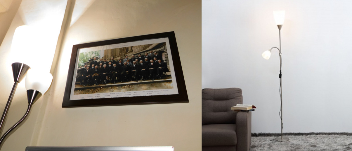
Figure 2: Larrissa Floor Lamp
I started with the PIR sensor as it is good at detecting general movement(it detects the change in motion). If during a long video call when I don’t move for a span of time, it will sent an OFF signal depending on the delay time configured. I experimented with the delay but it is hard to set an accurate delay to detect the movement. Any long delay value will keep the Lamp(s) ON for time unnecessary wasting the Power which was not my intention.
Another problem was any slight detection in the movement(happen when I was passing by the room without an intention of entering the room) caused the light to turn ON. I wanted the switching to be smart enough to check whether I am genuinely in the room(mostly working on my table). This is where HC-SRO4 ranging module was handy. It acts as a proximity sensor and in combination with the PIR, the switching of Lamps can be most reliable.
What if I want to manually control the switching of the Lamp(s)? This is were TSOP IR sensor came handy. I configured the Remote Control buttons for each Lamp.
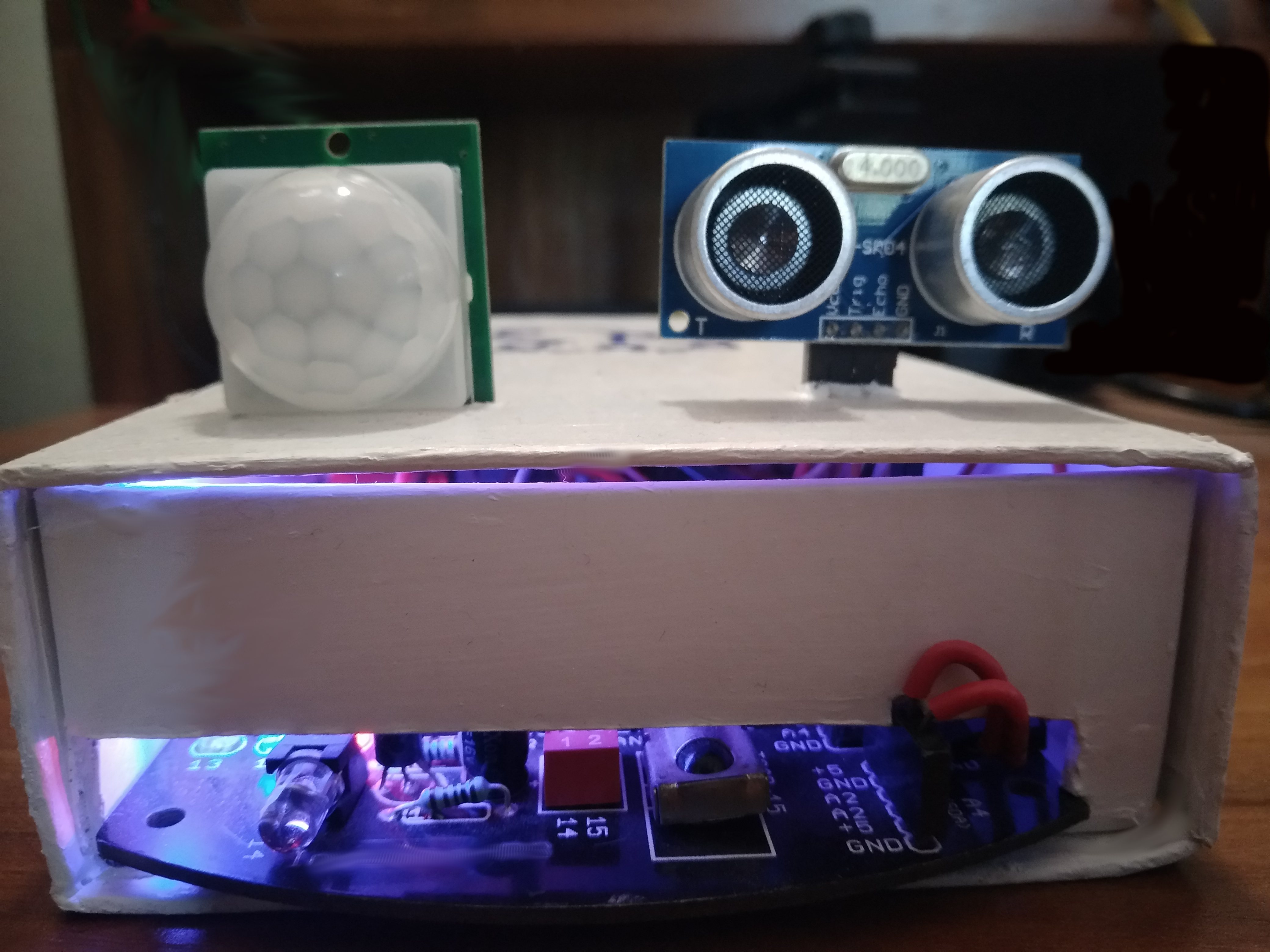
Figure 3: PIR & HC-SR04 Sensors at the front.
The 5v Relay: The Arduino is externally powered and as the Lamps are connected to the Arduino via the Relay, the Lamp will not operate if there is no Power to the Arduino. To avoid this the Lamps can be connected to the relay on NC(Normally Connected) mode. This allows operating the Lamps using the physical switch when Arduino is not powered.

Figure 4: Two channels of 5v relay are connected to Lamp1 & Lamp2.
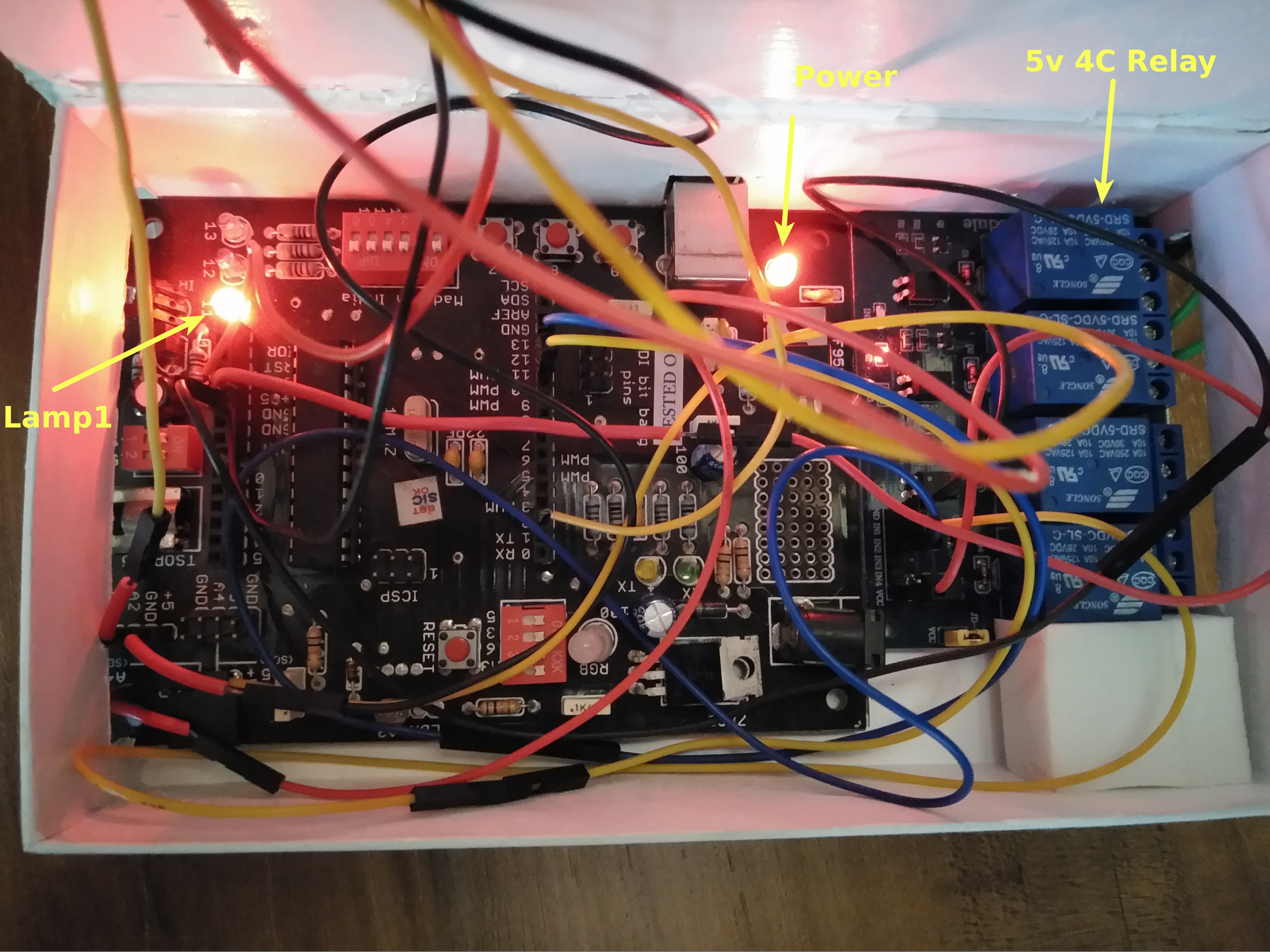
Figure 5: Wiring - Enclosed in the box. The LED on the left is Digital pin 11(Lamp1) whereas the LED on the right indicated the Power state of the board.
Debugging: The current implementation is in the form of Arduino sketch(ino)
which uses Arduino’s Serial function for easy debugging. For example,
1: Serial.begin(9600);
2: Serial.print(pir_state);
Combining the data from PIR & HC-SR04 sensors: I’ve mapped the Remote Control keys 1 & 2 to Lamp1 & Lamp2. The values for key 1 & 2 were 128 & 129 respectively. The same key should be pressed again to inverse the state of the Lamp i.e. pressing key 1 on the Remote Control will switch OFF the Lamp1 if it is ON.
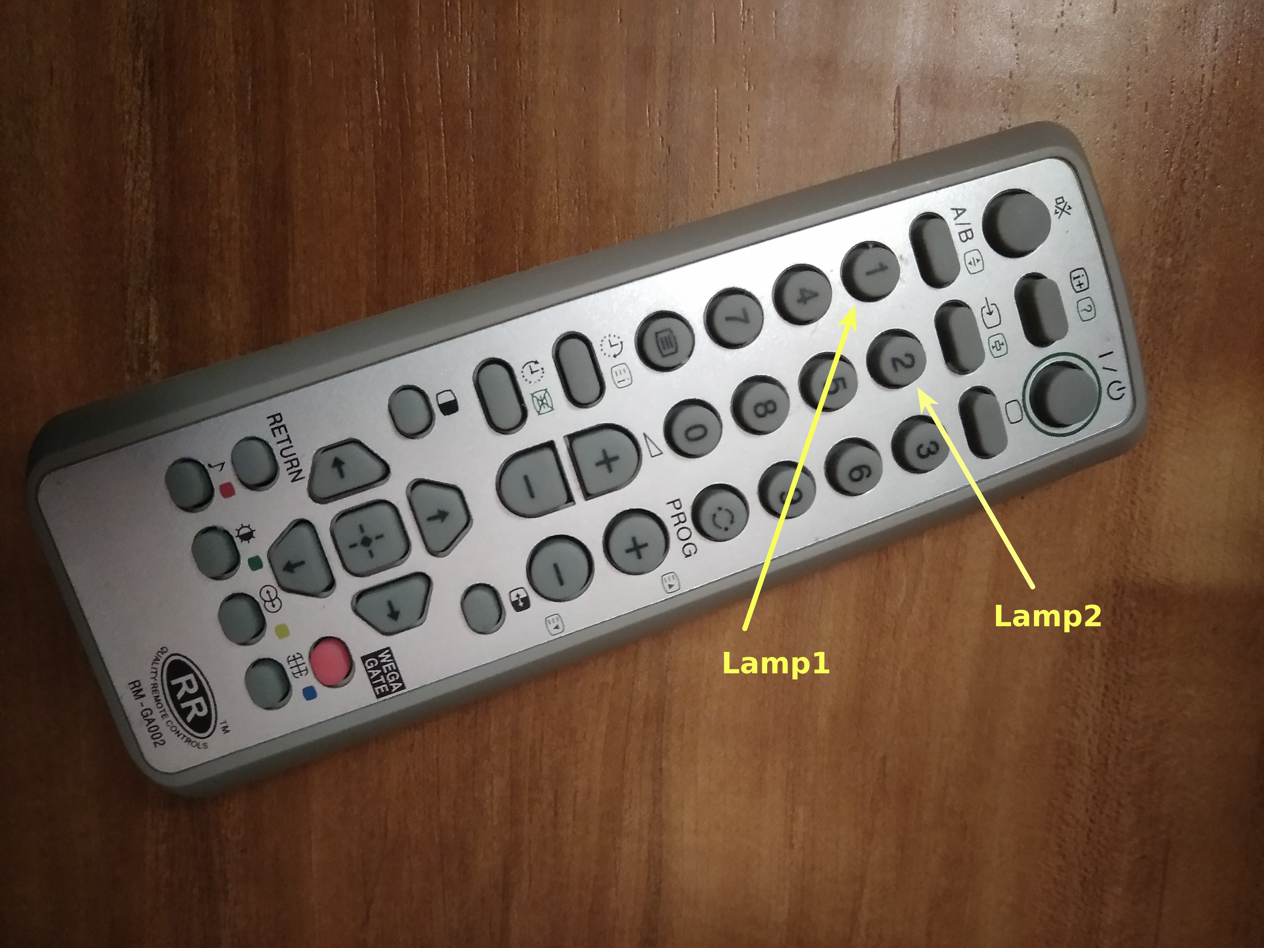
Figure 6: Remote Control - Button/key 1 & 2 are mapped to Lamp1 & Lamp2.
| Remote Control | Value | Lamp no. |
|---|---|---|
| Key 1 | 128 | 1 |
| Key 2 | 129 | 2 |
The signal from the Remote Control should be processed only when the PIR state is HIGH(motion detected). The following piece of code helps to achieve this,
 3: void loop() {
 4:     if(remote_val > 0 && pir_state == HIGH) {
 5:         if(remote_val == 128) {
 6:             lamp_1_state = !lamp_1_state;
 7:             digitalWrite(pin_lamp_1, lamp_1_state);
 8:         }
 9:         if(remote_val == 129) {
10:             lamp_2_state = !lamp_2_state;
11:             digitalWrite(pin_lamp_2, lamp_2_state);
12:         }
13:     }
Notice that line no. 6 & 10 are just inverting the Lamp state to ensure the same Remote Control key can be used to invert the Lamp state.
The delay time is set to 60 seconds after which the the PIR sensor will send a LOW signal to Lamp(s). The Proximity distance for HC-SR04 is set to 80CM which is enough for my current working position. This will ensure that the Lamp(s) will not turn OFF even if I stay in the stable state(no motion detect) during the Video calls as long as the proximity sensor detects value within 80CM range. It is also important to not reset the current ON state of the Lamps because the same state has to be restored when motion is detected. This is achieved using below logic,
14:     else if(pir_state == LOW && cm > hcsr04_distance_cm &&(lamp_1_state == 1 || lamp_2_state == 1)) {
15:         pir_low_counter++;      /* debounce */
16:         hcsr04_low_counter++;   /* debounce */
17:         if (pir_low_counter >= lamp_turn_off_delay && hcsr04_low_counter >= hcsr04_turn_off_delay) {
18:             turn_off();
19:             pir_low_counter = 0;
20:             hcsr04_low_counter = 0;
21:
22:             /*
23:              * We cannot reset lamp(s) state to 0 because we need to restore the
24:              * state as soon as the PIR & HCSR04 values are high
25:              */
26:         }
27:     }
28:     else if (pir_state = HIGH && pir_low_counter != 0 && cm < hcsr04_distance_cm && hcsr04_low_counter != 0) {
29:         pir_low_counter = 0;
30:         hcsr04_low_counter = 0;
31:     }
32:     else {
33:         restore_lamp_state(lamp_1_state, lamp_2_state);
34:         pir_low_counter = 0;
35:         hcsr04_low_counter = 0;
36:     }
37: }
Line no. 15 & 16 in the above code snippet are the counter variable to make sure that data from PIR & HC-SR04 sensor agree to switch OFF the Lamp(s). Finally the helper functions are defined as below,
 1: void turn_off() {
 2:     digitalWrite(pin_lamp_1, LOW);
 3:     digitalWrite(pin_lamp_2, LOW);
 4: }
 5:
 6: void restore_lamp_state(bool lamp_1_state, bool lamp_2_state) {
 7:     digitalWrite(pin_lamp_1, lamp_1_state);
 8:     digitalWrite(pin_lamp_2, lamp_2_state);
 9: }
10:
11: int remote() {
12:     int value = 0;
13:     int time = pulseIn(pin_tsop, LOW);
14:     if(time>2000) {
15:         for(int counter=0; counter < 12; counter++) {
16:             if(pulseIn(pin_tsop, LOW) > 1000) {
17:                 value = value + (1 << counter);
18:             }
19:         }
20:     }
21:
22:     /*
23:      * A remote press will normally generate 3 signals. Adding this delay
24:      * mitigates the noise.
25:      */
26:     delay(250);
27:
28:     return value;
29: }
30:
31: long microsecondsToInches(long microseconds) {
32:     return microseconds / 74 / 2;
33: }
34:
35: long microsecondsToCentimeters(long microseconds) {
36:     return microseconds / 29 / 2;
37: }
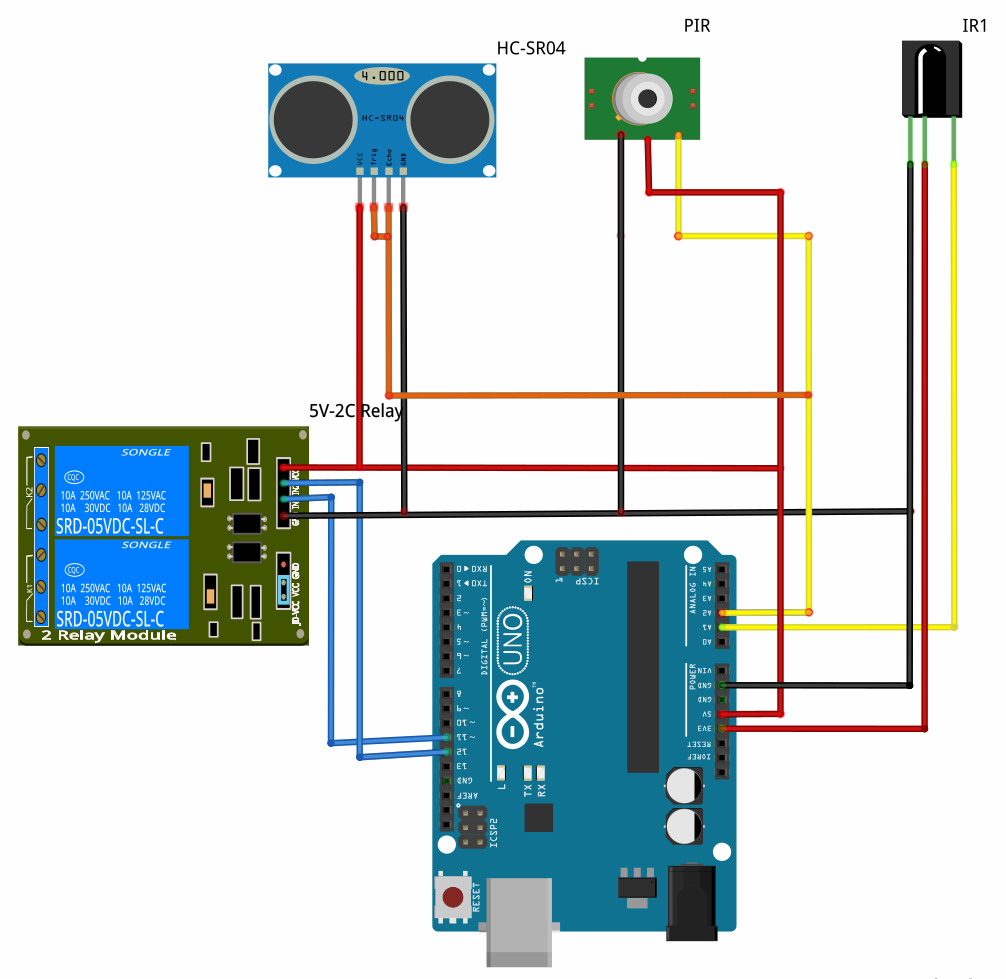
Figure 7: Circuit diagram - Digital pins 11 & 12 are used for Lamp1 & Lamp2.
Conclusion: So far the setup has worked well and as expected. The serial UART debugging does helps a lot to fine tune the values. The setup is currently powered by USB and I plan to use a stable battery source backed by Solar Power. I also want to include the room temperature sensor to provide feedback to control AC/Fan via IR LED. For that, I will have to play with the Remote Controls to find the exact value to signal the devices using the current setup. If things get complicated especially the connecting wires, I will go for a custom PCB design.
Future work:
- Convert .ino into Pure AVR-C implementation to improve optimization.
- Add a temperature sensor for controlling Air Conditioner/Fan. This requires interfacing IR LED.
- Solar Powered battery supply.
The current source code is available at GitLab/lamp.